توضیحات
|
Type
|
Material
Thickness
mm
|
F in KN
KN |
Weight
Kg/100 pcs
|
Item No.
|
| WUB B 11 PG | 1.5 & 5 | 1.5 | 10646 | |
| WUB B 16 PG | 1.5 & 5 | 1.5 | 10648 | |
| WUB B 21 PG | 1.5 & 5 | 1.5 | 10650 | |
| WUB B 31 PG | 2 & 5 | 1.5 | 10652 | |
| WUB B 41 PG | 2 & 5 | 1.5 | 10654 | |
| WUB B 51 PG | 2 & 5 | 1.5 | 10656 | |
| WUB B 61 PG | 2 & 5 | 1.5 | 10658 | |
| WUB B 11 HDG | 1.5 & 5 | 1.5 | 10660 | |
| WUB B 16 HDG | 1.5 & 5 | 1.5 | 10662 | |
| WUB B 21 HDG | 1.5 & 5 | 1.5 | 10664 | |
| WUB B 31 HDG | 2 & 5 | 1.5 | 10666 | |
| WUB B 41 HDG | 2 & 5 | 1.5 | 10668 | |
| WUB B 51 HDG | 2 & 5 | 1.5 | 10670 | |
| WUB B 61 HDG | 2 & 5 | 1.5 | 10672 | |
| WUB B 11 SS | 1.5 & 5 | 1.5 | 10674 | |
| WUB B 21 SS | 1.5 & 5 | 1.5 | 10676 | |
| WUB B 31 SS | 2 & 5 | 1.5 | 10678 | |
| WUB B 41 SS | 2 & 5 | 1.5 | 10680 | |
| WUB B 51 SS | 2 & 5 | 1.5 | 10682 | |
| WUB B 61 SS | 2 & 5 | 1.5 | 10684 |
Hot-dip galvanized HDG
PG Pre-galvanized
SS Stainless steel
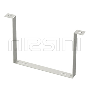
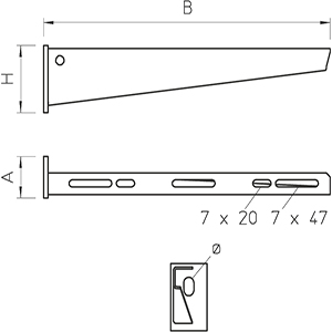
Dimensions
|
Type
|
Dimension
B
mm
|
Dimension
A
mm
|
Dimension
H
mm
|
Hole
∅
mm
|
| WUB B 11 |
110 | 40 | 50 | 11 |
| WUB B 16 |
160 | 40 | 55 | 11 |
| WUB B 21 |
210 | 40 | 60 | 11 |
| WUB B 31 |
310 | 40 | 65 | 11 |
| WUB B 41 |
410 | 40 | 70 | 11 |
| WUB B 51 | 510 | 40 | 75 | 11 |
| WUB B 61 | 610 | 40 | 80 | 11 |
بارگذاری (Loading)
نمودار بارگذاری براکت ، مدل WUB B
Load diagram, bracket, type WUB B

1 Bending of the bracket tip at permitted bracket load
2 Permitted bracket load in kN without man load
Load curve with bracket lengths in mm
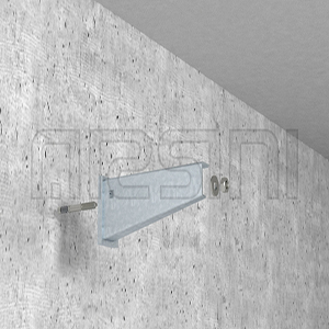
مقادیر تحمل بار براکت WUB B با پیچ مهار مخصوص – نصب بر روی دیوار
Characteristic anchor bolt load values for bracket WUB B – Wall fastening
| Max. load F (KN) |
 |
|||||||
| 610 | 510 | 410 | 310 | 210 | 160 | 110 | Bracket width (mm) |
|
| Anchor bolt type | ||||||||
| 0.45 | 0.5 | 0.55 | 0.65 | 0.8 | 0.9 | 1.1 | WAB 8/75 | |
| 0.8 | 0.85 | 0.95 | 1.1 | 1.4 | 1.5 | 1.5 | WAB 10/90 | |
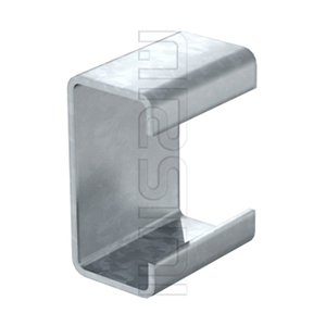
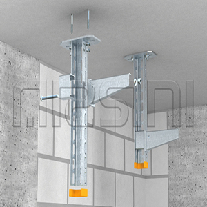
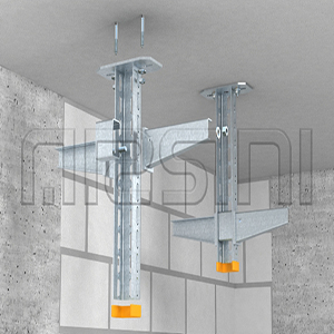
مقادیر تحمل بار براکت WUB B با پیچ مهار مخصوص – نصب بر روی U ساپورت آویز
Characteristic anchor bolt load values for bracket WUB B – suspended U support
| Max. load F (KN) |
 |
||||
| 410 | 310 | 210 | 110 | Bracket width (mm) |
|
| U Support type | |||||
| 1.3 | 1.3 | 1.5 | 1.5 | US 3 P / 20-60 | |
| 1.3 | 1.3 | 1.5 | 1.5 | US 3 P / 70-120 | |
| 1.5 | 1.5 | 1.5 | 1.5 | US 5 P / 20-60 | |
| 1.5 | 1.4 | 1.5 | 1.5 | US 5 P / 70-120 | |
Max. total load F = cable weight + cable tray + bracket. The load capacity values increase considerably when used in uncracked concrete. The values given are based on concrete of strength class C20/25. Observe the installation conditions of the DIBt approval (anchors).