توضیحات
|
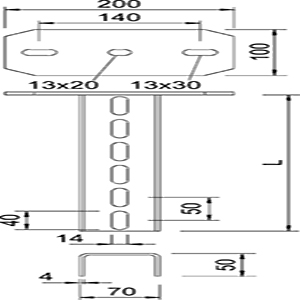
Type
|
Length
mm
|
Material
Thickness
mm
|
Tensile
Load
KN |
Weight
Kg/100 pcs
|
Item No.
|
| US 7 P 20 HDG | 200 | 4 & 6 | 11 | 10522 | |
| US 7 P 30 HDG |
300 | 4 & 6 | 11 | 10524 | |
| US 7 P 40 HDG |
400 | 4 & 6 | 11 | 10526 | |
| US 7 P 50 HDG |
500 | 4 & 6 | 11 | 10528 | |
| US 7 P 60 HDG |
600 | 4 & 6 | 11 | 10530 | |
| US 7 P 70 HDG |
700 | 4 & 6 | 11 | 10532 | |
| US 7 P 80 HDG |
800 | 4 & 6 | 11 | 10534 | |
| US 7 P 90 HDG |
900 | 4 & 6 | 11 | 10536 | |
| US 7 P 100 HDG |
1000 | 4 & 6 | 11 | 10538 | |
| US 7 P 120 HDG |
1200 | 4 & 6 | 11 | 10540 | |
| US 7 P 200 HDG |
2000 | 4 & 6 | 11 | 10542 | |
| US 7 P 300 HDG | 3000 | 4 & 6 | 11 | 10544 | |
| US 7 P 20 SS | 200 | 4 & 6 | 11 | 10546 | |
| US 7 P 30 SS | 300 | 4 & 6 | 11 | 10548 | |
| US 7 P 40 SS | 400 | 4 & 6 | 11 | 10550 | |
| US 7 P 50 SS | 500 | 4 & 6 | 11 | 10552 | |
| US 7 P 60 SS | 600 | 4 & 6 | 11 | 10554 | |
| US 7 P 70 SS | 700 | 4 & 6 | 11 | 10556 | |
| US 7 P 80 SS | 800 | 4 & 6 | 11 | 10558 | |
| US 7 P 90 SS | 900 | 4 & 6 | 11 | 10560 | |
| US 7 P 100 SS | 1000 | 4 & 6 | 11 | 10562 | |
| US 7 P 120 SS | 1200 | 4 & 6 | 11 | 10564 | |
| US 7 P 200 SS | 2000 | 4 & 6 | 11 | 10566 |
Hot-dip galvanized HDG
SS Stainless steel
بارگذاری (Loading)
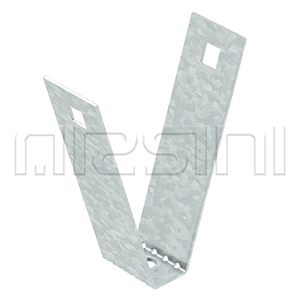
نمودار بارگذاری نگهدارنده U ، مدل US 7 P
Loading diagram, U support, type US 7 P

1 Bending of the end of the suspended support at permitted bracket load
2 Permitted bracket load in kN without man load
3 Bracket length in mm
Load curves with support lengths in mm
مقادیر تحمل بار نگهدارنده آویزی US 7 P با پیچ مهار مخصوص – بار یک طرفه
Characteristic anchor bolt load values for US 7 P suspended support – Single-sided load
| Max. load F (KN) |
 |
||||||
| 610 | 510 | 410 | 310 | 210 | 110 | Bracket width (mm) |
|
| Anchor bolt type | |||||||
| 1.75 | 2 | 2.25 | 2.5 | 3.25 | 4.25 | WAB 10/90 | |
| 3 | 3.5 | 4 | 4.5 | 5.5 | 7.25 | WAB 12/110 | |
مقادیر تحمل بار نگهدارنده آویزی US 7 P با پیچ مهار مخصوص – بار دو طرفه
Characteristic anchor bolt load values for US 7 P suspended support – Double-sided load
| Max. load F (KN) |
 |
||||||
| 610 | 510 | 410 | 310 | 210 | 110 | Bracket width (mm) |
|
| Anchor bolt type | |||||||
| 4.5 | 4.8 | 5.25 | 5.75 | 6.25 | 7.25 | WAB 10/90 | |
| 8 | 8.5 | 9 | 10 | 11 | 11 | WAB 12/110 | |
Max. total load F = cable weight + cable tray + bracket + suspended support. The tabular values for double-sided loads take the available axis spacing ai = 14 cm into account. The load capacity values increase considerably when used in uncracked concrete. Observe the load capacity of the brackets (diagram) and the installation conditions of the DIBt approval (anchors).